Development of Optimal Conditioning Method to Improve Economic Efficiency of Polymer Electrolyte Membrane (PEM) Fuel Cells


School of Mechanical Engineering, Chung-Ang University, Seoul 06974, Korea
*
Author to whom correspondence should be addressed.
Energies 2020, 13(11), 2831; https://doi.org/10.3390/en13112831
Submission received: 27 April 2020
/
Revised: 18 May 2020
/
Accepted: 29 May 2020
/
Published: 2 June 2020
(This article belongs to the Special Issue Polymer Electrolyte Membrane Fuel Cells and Electrolyzers)
Abstract
:This study presents an economical conditioning method for polymer electrolyte membrane (PEM) fuel cells through a parametric study investigating the factors affecting online conditioning methods. First, we compared the operating conditions between constant current (CC) mode and constant voltage (CV) mode conditioning to understand the effects of current and potential differences on conditioning. We found that CV mode conditioning is at least one hour faster at the same load. This is because unlike CV mode conditioning, which has a constant load over the entire range of the membrane electrode assembly (MEA), CC mode conditioning features current flow through the existing passage of the pre-activated triple phase boundary of the MEA so that the electronic load is not entirely used in the conditioning process. Second, the optimization of CV mode conditioning was conducted by controlling the conditioning temperature. Lastly, the economics of the proposed method were analyzed by comparing it with existing conditioning methods. Using this optimal conditioning method can reduce the consumption of hydrogen during conditioning by ~87.5% compared to previous methods. The findings from this study provide the means to lower the actual production cost of fuel cells, thereby ensuring market access.
1. Introduction
Clean fuel cells based on non-fossil-fuel sources have been in the limelight recently owing to their advantage of reduced environmental pollution [1]. Among them, the polymer electrolyte membrane (PEM) fuel cell can be applied to a wider range of fields than other types of fuel cells due to its low operating temperature and short startup time. A newly fabricated PEM fuel cell needs a break-in/conditioning/incubation period in order to be activated and achieve its best performance [2]. Generally, during this conditioning period, the cell performance gradually increases and then reaches a plateau without further increase. The mechanism for the conditioning process, however, is not yet fully understood, so this process may take many hours or days depending on the operating conditions. Accordingly, the production time is increased during mass production, and a large amount of hydrogen is used, thereby increasing the unit cost of the fuel cell stack [3]. Therefore, it has become important to identify the fuel cell conditioning mechanism in order to minimize the time needed for conditioning fuel cells to achieve economic efficiency [4].
Conditioning refers to the process of maximizing the power of the fuel cell. Three possible theories have been put forward to explain conditioning phenomena [5]: activation of the catalyst [6], removal of impurities [7] and ensuring passage of hydrogen ions [8]. Research on conditioning methods is divided into offline and online conditioning depending on the before- and after-assembly process of the fuel cell. Off-line conditioning involves conditioning of the catalyst-coated membrane (CCM) or electrodes before they are assembled into the cell/stack. Palanichamy et al. [9] proposed an electrochemical technique for conditioning the membrane electrode assembly (MEA) by immersion in dilute H2SO4. The study reported improvements to the current density of PEM fuel cells due not only to chemical oxidation (e.g., PtO formation and O2 evolution), but also to the cleaning process of the Pt surface. For example, the current density increased about 16% at 0.6 V compared to without conditioning [10]. Another study by Qi et al. [11] proposed a method to treat electrodes or MEAs using hot water or steam before they are assembled into a stack. The study reported that treatment of electrodes or CCMs by either boiling in water or steaming in a household pressure cooker for as short as 10 min could drastically increase their performance when tested in PEM fuel cells afterwards (e.g., current density increased about 11% at 0.6 V compared to without being steamed). A similar procedure of exposing the MEA to saturated steam at atmospheric pressure was patented by Bradley [12] in order to pre-condition the MEA. All these studies have shown that MEA hydration is an important factor in conditioning. In the case of offline conditioning, however, cannot perform all three of the above processes, only one-step process is included: e.g., only one-step process of ‘removal of impurity’ with sulfuric acid or of ‘ensuring the passage of hydrogen ions’ through humidification. Therefore, it is necessary for online conditioning to reach the highest possible power density. Because of this, the conditioning process still requires a relatively long time.
Traditional online conditioning methods include current control, potential control and temperature control. Current control investigations have indicated that forced conditioning at varied currents can activate the MEA [13,14,15]. Xie et al. [14] conducted research on a constant current (CC) mode of 25 A in order to activate one cell. The test cell conditions featured a 25 cm2 electrode with a Nafion NRE-211 membrane, and the conditioning lasted more than 6 h. Kim et al. [13] conducted research using a CC density of 0.1 A/cm2. The tested cell was a direct methanol fuel cell (DMFC) with a Nafion 117 membrane, and the conditioning lasted up to 50 h. Furthermore, many investigations of potential control with variations in duration, load cycle and cell conditions have been conducted [3,4,7,16]. For example, Ko et al. [3] compared the results obtained after 3 h of conditioning using constant voltage (CV) modes of 0.4 V and 0.6 V, as well as open-circuit voltage (OCV). They found that when conditioning was conducted at 0.4 V, potential control was 6.1% higher than conditioning at 0.6 V; therefore, low potential activated the cell faster. Murthy et al. [4] conducted studies on potential cycling by applying a first external load of approximately 0.6 V for approximately 20 min, followed by removing the external load for approximately 2 min, and then applying a second external load of approximately 0.3 V for approximately 20 min. The conditioning process reached 90% completion and lasted over 4 h. Moreover, temperature control has been performed together with current/potential control; for example, Qi et al. [17,18,19] provided an effective, fast conditioning procedure by exposing the fuel cell to elevated temperatures of aggressive conditions (75, 95, and 90 °C) combined with elevated pressure. The conditioning process was completed within 2 h. Studies on conditioning methods have been carried out using various methodologies; however, studies on shortening the conditioning time are insufficient. Therefore, it is necessary to identify the optimal conditioning method by considering the mechanism of conditioning through a parametric study designed to shorten the conditioning time and also improve economic efficiency.
To this end, we have conducted a parametric study to develop an optimal economically viable online conditioning method for PEM fuel cells. First, the optimal operating conditions of CC and CV mode conditioning were examined to understand the effects of current and potential differences on conditioning. Second, optimization of CV mode conditioning was conducted by controlling the conditioning temperature. Lastly, economics of the proposed optimal conditioning method were analyzed by comparing it with previous conditioning methods. The findings from this study provide the means to lower the actual production cost of the fuel cell, thereby ensuring market access.
2. Methodology
2.1. Principal of PEM Fuel Cell Conditioning
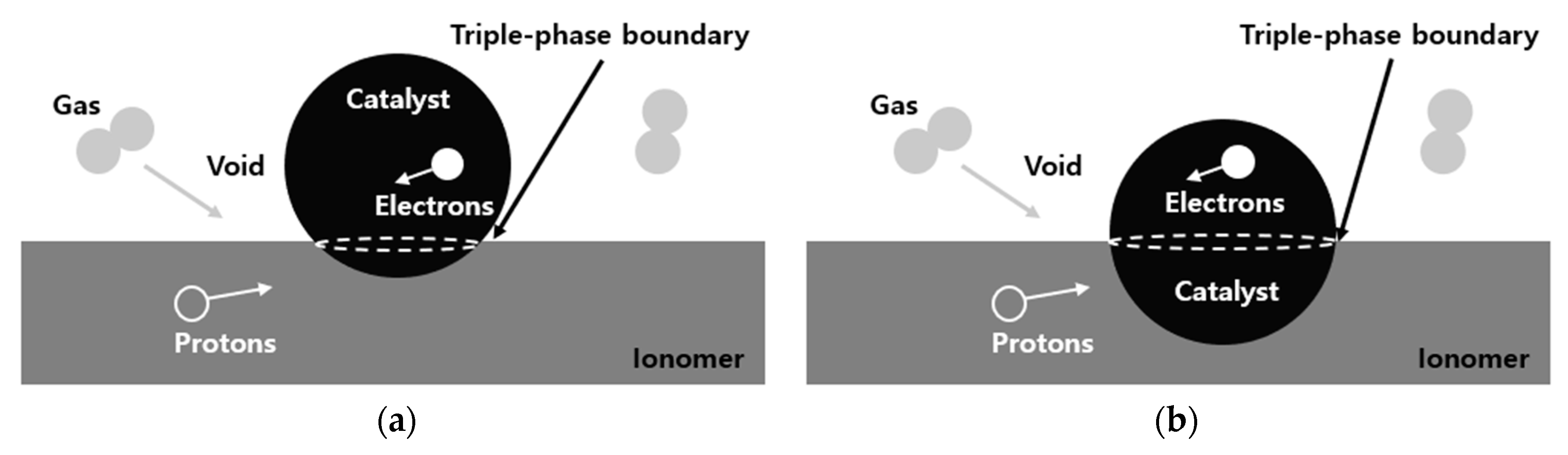
Several theories have been put forward to explain conditioning phenomena [5] such as removal of impurities by catalysts and humidification of membrane electrode assemblies (MEAs). In this study, the break-in/conditioning/incubation process is referred to as ‘conditioning’. Firstly, the conditioning of the fuel cell is known to have advantageous effects on the catalyst [4,7]. During the conditioning process, impurities introduced when manufacturing the MEA are removed, and catalysts that do not participate in the reaction are activated. Second, the conditioning of fuel cells creates a channel for hydrogen ions. Since the membranes are initially dry, the membrane is hydrated during the conditioning period, so the electrolyte contained in the electrodes ensures the passage of hydrogen ions [8,20,21]. Although these theories can explain one portion of the conditioning process, they cannot explain why online conditioning should be necessary after offline conditioning. Therefore, we have focused on the role of conditioning as a means of improving the ionic conductivity of the catalyst layer (CL) [22,23]. That is, the conditioning process should activate the electrodes of the MEA, increasing the triple phase boundary (TPB) where the electrochemical reaction has occurred.
A schematic of the TPB of the MEA is shown in Figure 1. During conditioning, the TPB expands; this is explained by the theory of not only the introduction of Nafion electrolytes (hereafter; Nafion) into the CL [22,23] but also by the carbon oxidation reaction (COR) of the carbon support. This Nafion intrusion into the catalyst layer is thought to result from the hydration of the membrane. Swelled Nafion surrounds Pt particles, so that the TPB increases. The TPB increase is also related to the COR of the carbon support consisting of Nafion. In some cases, the carbon support has a defect site consisting of C+ which is prone to reversible electrochemical oxidation, forming C–OH groups. Through this reaction, carbon surface oxides (COsurf) can be formed and become oxidized to CO2, a process which is illustrated in Table 1 [24,25]. In this conversion process, the carbon support is lost, and the TPB is increased at the catalyst–ionomer–gas conversion point. COR is susceptible at relatively high potential (>0.6 V) [26], and the increase in the TPB enhances the performance of the PEM fuel cell. The performance reaches a maximum value and plateaus after a certain amount of time passes.
2.2. Experimental Setup
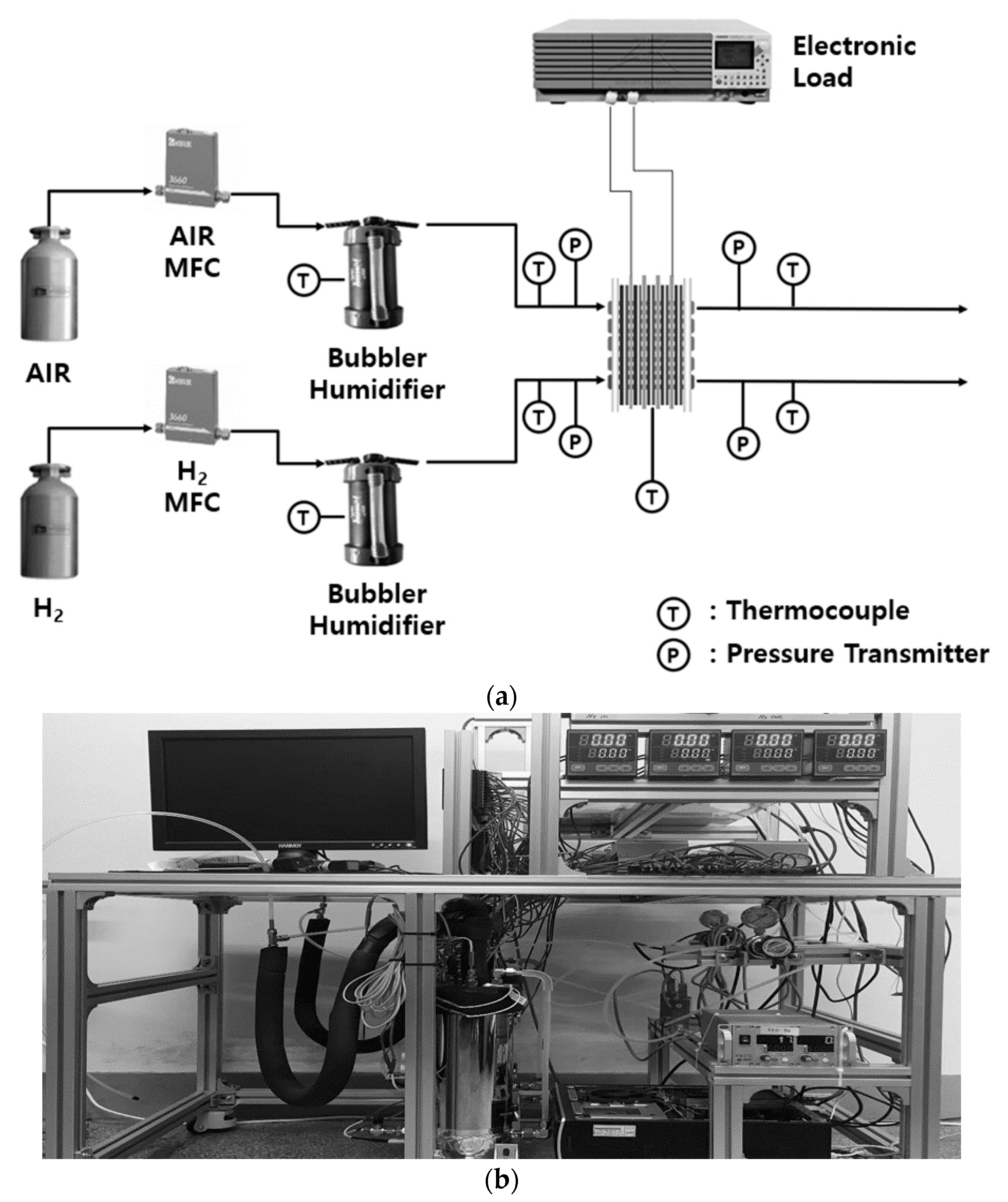
The fuel cell (unit cell, CNL) was assembled by arranging gas diffusion layers (GDLs) (39BB, SGL) sequentially with MEA (VFM-P25P-N, Vinatech) between graphite plates that were formed with a serpentine flow path, and then fastened under constant pressure. MEA, the geometric area of the electrode was 25 cm2, with Pt loading of 0.4/0.4 mg/cm2 (anode/cathode). The experiment was conducted with a single cell, and performance of the cell was evaluated using electronic load (PLZ664WA, Kikusui). Hydrogen and air were controlled at a constant flow rate through a mass flow controller (MFC, Sehwa High Tech), humidified through a bubbler (CNL) and supplied to the fuel cell. The temperature of the gas was controlled by surrounding the pipe with heating tapes. The heating tapes were connected to the indicator (HX9, Hanyoung Nux) to maintain the operating temperature. Thermocouples were installed at the inlet of the cell, middle of the cell, outlet of the cell and humidifier line. Seven indicators precisely control the temperature of the gas. The error was ±0.5%. The gas was humidified through the bubbler. The heating tapes were wound outside the bubbler, and the thermocouple was located at the middle of the bubbler. The relative humidity was determined through comparison between the gas temperature and the bubbler temperature. The gas pressure at the fuel cell inlet and outlet were measured. A schematic of the PEM fuel cell experiment and photograph of the experimental equipment are shown in Figure 2a,b respectively.
In order to investigate the condition of the fuel cell, experiments were conducted in the order of CC mode followed by CV mode. Since the hydration of the membrane is important for conditioning [8,21], the experiment was conducted at 100% relative humidity. First, in order to know the end point of conditioning, a membrane conditioning experiment was performed in various ways. It was determined that the conditioning was terminated when the current value at 0.6 V was 20% higher than the initial current value; this process is hereafter referred to as ‘complete conditioning’. In the case of the CC mode, three experiments were conducted at 0.03 A/cm2, 0.60 A/cm2 and 1.32 A/cm2, respectively. In the CV mode, experiments were performed at 0.3 V, 0.6 V and 0.9 V, each (with the highest voltages being at 1.32 A/cm2, 0.60 A/cm2, 0.03 A/cm2, respectively). The stoichiometric number was 1.5 at the anode and 2.0 at the cathode, respectively. The fuel cell performance was measured every 30 min. In this way, we compared CC and CV mode conditioning, following which the optimization of the conditioning process was developed by varying the temperature. The optimal conditioning method was then selected based on economic efficiency.
3. Results and Discussion
3.1. Comparison of PEM Fuel Cell Conditioning between CC and CV Modes
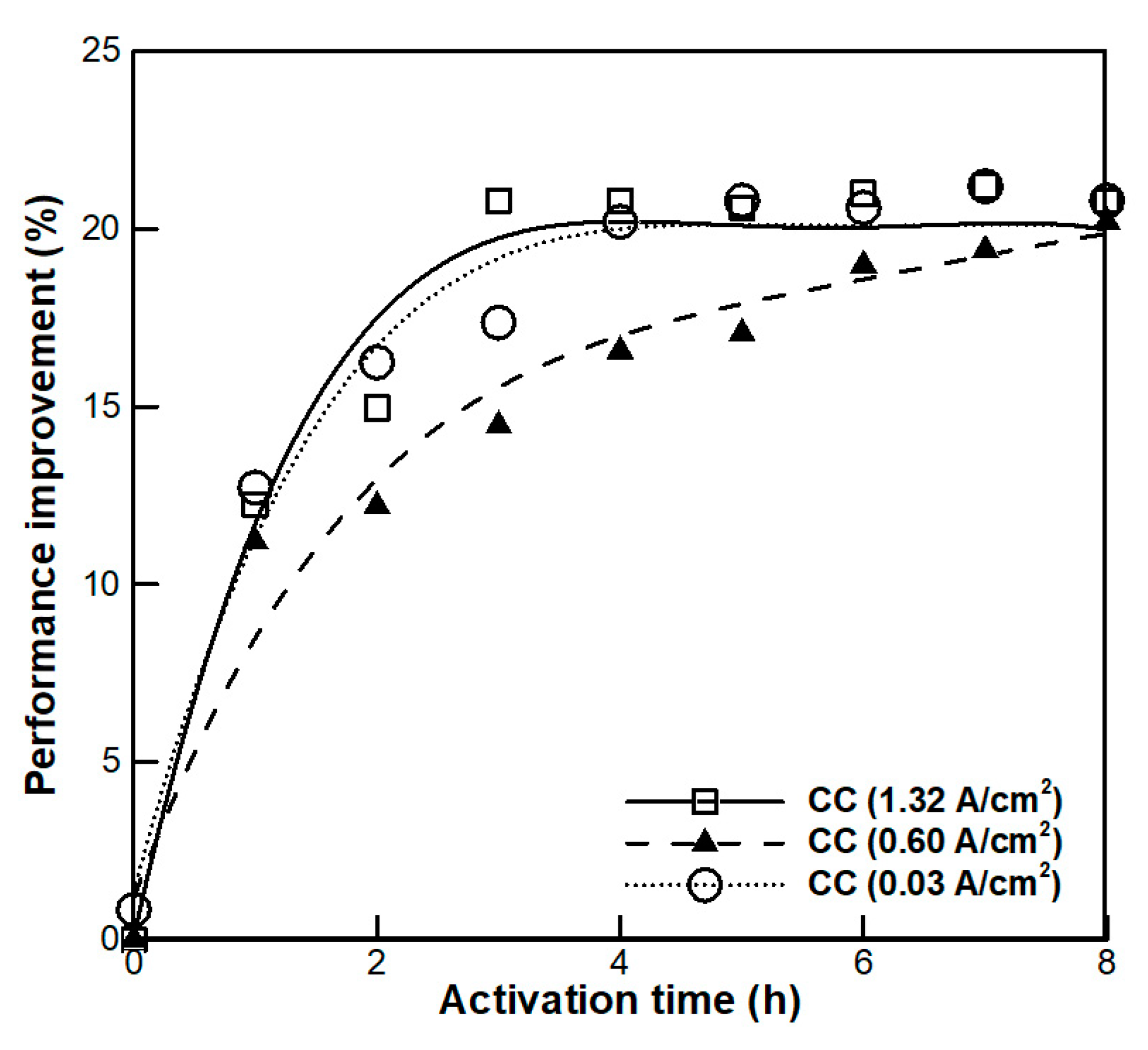
Experiments on CC mode conditioning were conducted under various current conditions. The operating temperature was kept constant at 80 °C. In the case of CC mode conditioning, time required for complete conditioning is shown in Figure 3. Performance improvement (PI) was calculated as follows:
where iinitial is the initial current density at 0.6 V and i is measured current density at 0.6 V. Conditioning through the CC mode required 3 h at 1.32 A/cm2, 4 h at 0.03 A/cm2 and 8 h at 0.60 A/cm2. The higher the electronical load (i.e., the higher the current density), the faster the conditioning occurred. This is because as the amount of applied load increases, the amount of catalysts engaged in the electrochemical reaction is greater. The use of more catalysts leads to the activation of catalysts that did not originally participate in the reaction [7], and causes increase of the TPB. Interestingly, we also observed that the lower the electronical load (i.e., the lower the current density), the faster the conditioning occurred. This is because as the applied electronic load decreases, the potential difference increases. When the potential difference becomes large, the carbon surface oxidation reaction occurs at the carbon defect site, and the carbon supporting the catalyst disappears as CO2, as described in Table 1 [24,25]. This causes the catalyst to relocate to the ionomer and enlarges the area of the TPB. Therefore, the time required for conditioning is reduced.
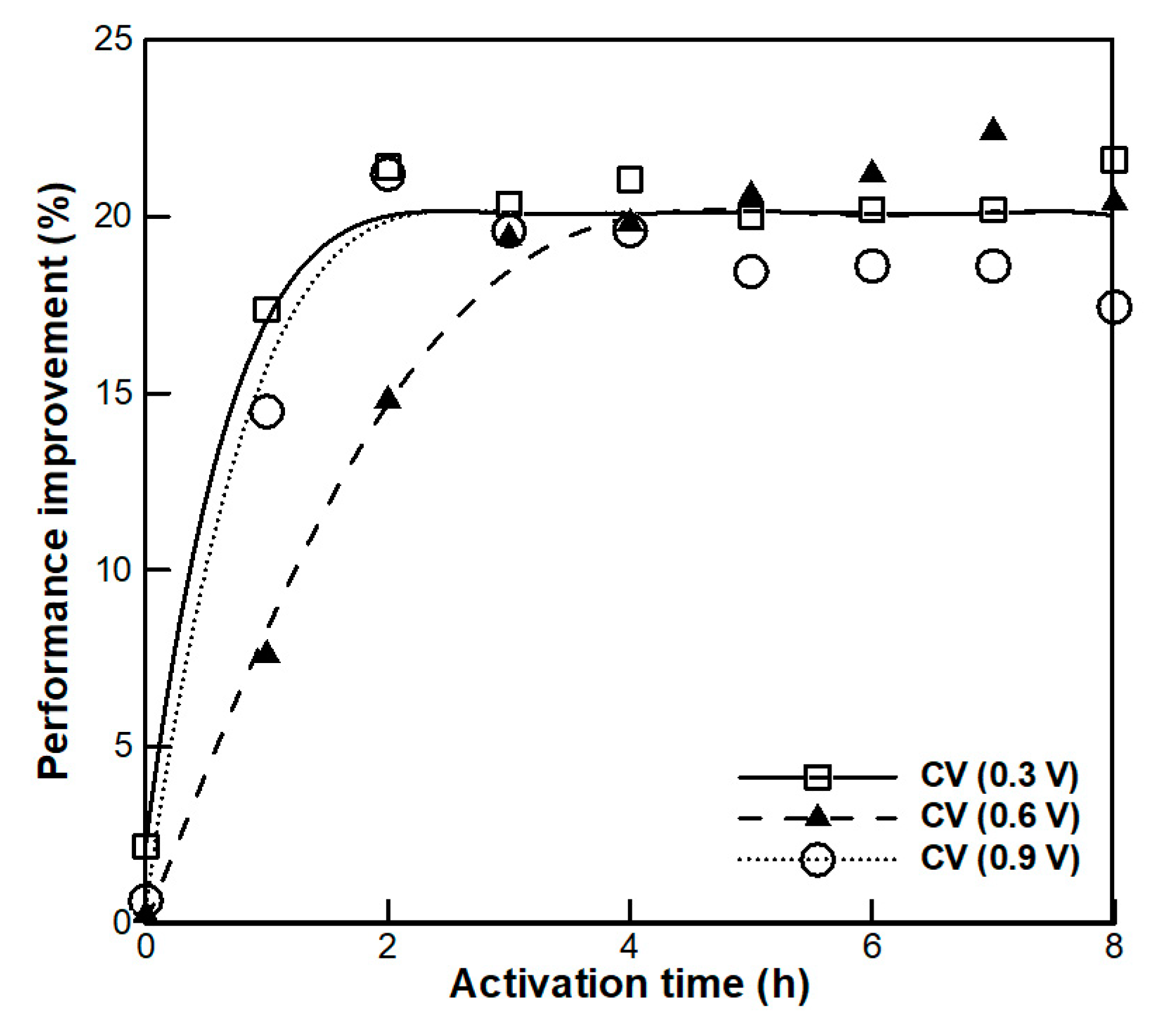
Experiments on CV mode conditioning were conducted under various potential differences. To compare the results with those of the CC mode, the same experimental conditions were used as with the CC mode and PI was calculated using Equation (1). In the case of conditioning using the CV mode, as shown in Figure 4, conditioning finished in the order of 0.3 V, 0.9 V and 0.6 V and required approximately 2 h at 0.3 V and 0.9 V and 5 h at 0.6 V. We observed that as the potential difference became higher, the conditioning occurred at a higher rate. This is because, at a high potential difference, the COR is active and the CO2 emission reaction rate is increased [24]. As a result, the carbon support is lost, and the bond between the catalyst and the ionomer increases; resulting in TPB formation through rearrangement of the catalyst and leading to higher performance, as is shown in Table 1 [24,25]. Interestingly, we also observed that as the potential difference was lowered further, the conditioning again occurred at a higher rate. This is because, at low potential differences, high current densities occur, increasing the amount of catalysts engaged in the electrochemical reaction by activating additional catalysts which had not originally participated in the reaction. Therefore, faster conditioning is achieved.
As shown in Figure 4, for conditioning using a high potential difference, the cell performance decreased after 3 h. This is because at a high potential difference, the higher COR rate leads to excessive corrosion of the carbon support, which leads to catalyst loss and, therefore, ultimately leading to the degradation of fuel cell performance [27]. In order to prevent this, it is necessary to adjust the proper conditioning time when conditioning with a high potential difference. Nevertheless, PEM fuel cells are more efficient when conditioned using high potential differences. Assuming conditioning is conducted for the same amount of time, the amount of hydrogen consumed when driving at 0.9 V is approximately 3.3 times less than that when driving at 0.3 V. Therefore, if conditioning is performed at 0.9 V, high economic efficiency can be achieved.
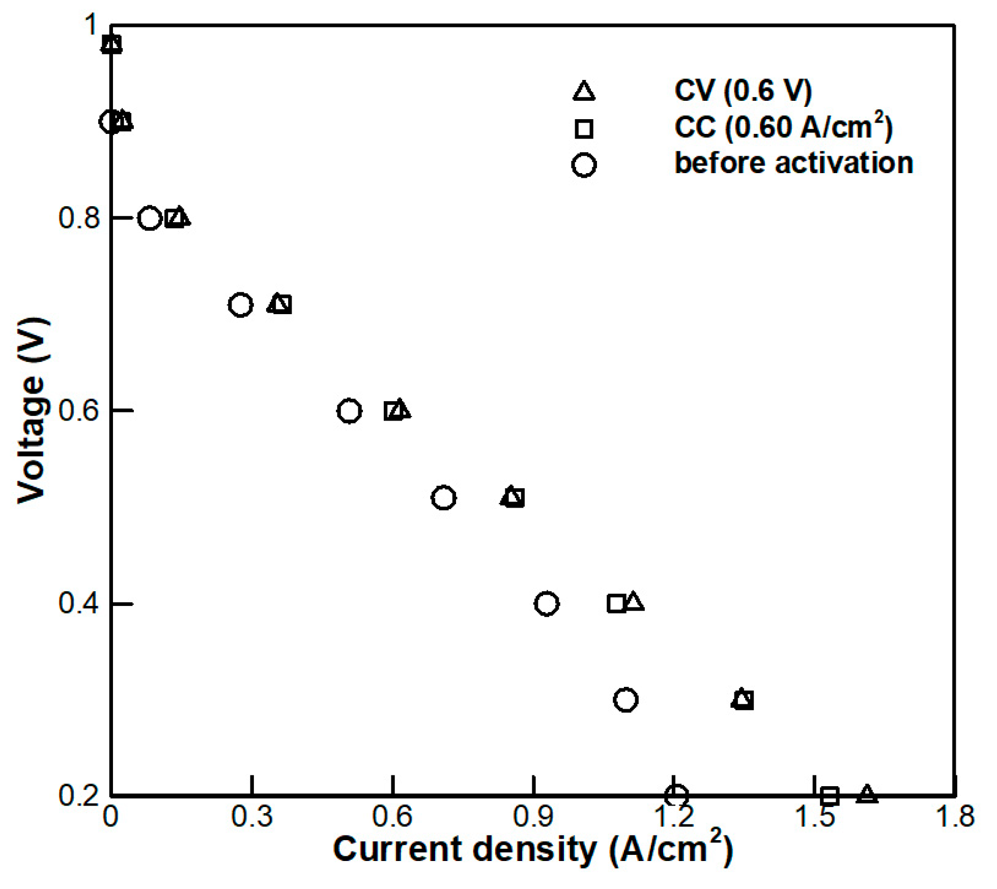
Figure 5 shows a comparison of the performance of the PEM fuel cell between CC and CV mode conditioning. After conditioning in both CC and CV modes, OCV increased by approximately 9.01%. The PI of the PEM fuel cell in the CV mode was 4.07% lower at 0.7 V, 1.19% lower at 0.5 V and 0.55% lower at 0.3 V, compared to the CC mode. However, it was 2.76% higher at 0.6 V and 3.75% higher at 0.4 V. When conditioned in the CC and CV modes, the difference in PI was less than 4.1%, so there was no difference in performance after conditioning even if conditioning was performed in either the CC or CV mode. The reason for this is that the only difference in driving methods between the CC mode and CV mode is whether a voltage is applied or a current is applied.
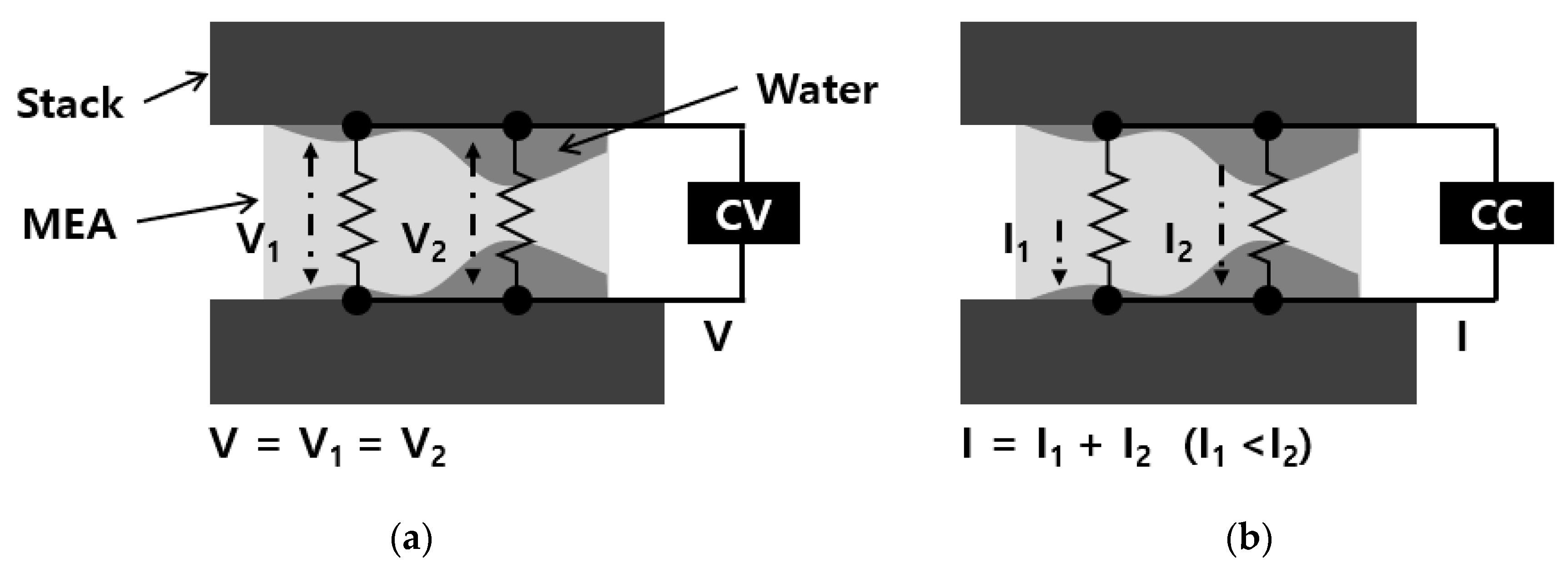
Table 2 shows the time required for complete conditioning. Conditioning in the CV mode was faster than that in the CC mode. This difference in time consumption needed for conditioning is related to the different operating mechanisms between the CC and CV modes. The principle of difference between the CV and CC modes in the conditioning process is described in Figure 6. In the CC mode, a constant current is applied, which mostly flows into the already activated channel of hydrogen ions in the MEA caused by hydration. Thus, local relocation of the catalysts can easily occur. However, in the CV mode, when a potential difference is applied to the cell, that same potential difference is applied to the whole area of the MEA regardless of hydration level. Therefore, in the CV mode, an environment is created in which a wider range of catalysts can be rearranged. Thus, it is faster to use the CV mode for conditioning. Based on these findings, we infer that it is best to condition the PEM fuel cell in the CV mode at 0.9 V to achieve the greatest economic efficiency.
3.2. Optimization of CV Mode Conditioning
3.2.1. CV Mode Conditioning Depending on Operating Temperature
In order to investigate the effect of operating temperature on the conditioning process, experiments were conducted at 65 °C, 80 °C and 95 °C, respectively. It was confirmed through the experiment described in Section 3.1 that the CV mode is more effective than the CC mode in the case of conditioning. Based on this finding, further experimentation was conducted in the CV mode with the conditioning voltage of 0.6 V. Because conditioning was relatively slow at 0.6 V, we found significant differences on varying the temperature. As shown in Figure 7, the time required for complete conditioning was 4 h at 95 °C, 5 h at 80 °C and 8 h at 65 °C, thereby indicating that the fastest conditioning was achieved at 95 °C. This is because as the temperature increases, the electrochemical reaction becomes more active and this can be explained by examining the behavior of the reversible thermodynamic potential depending on temperature, as shown in the Nernst Equation:
where E0 is the standard electrochemical cell potential, F is Faraday’s constant and R is the universal gas constant. pH2O, pH2 and pO2 are the partial pressures of H2O, H2 and O2, respectively and T is the temperature. For this reason, as the temperature becomes higher, the amount of catalysts used for the electrochemical reaction increases, and the time needed to activate non-participating catalysts is decreased. Therefore, conditioning is more effective at a high temperature. Based on these results, we suggest that in order to achieve complete conditioning faster, the PEM fuel cell should be conditioned at 95 °C.
3.2.2. Economic Analysis of Optimized CV Mode Conditioning
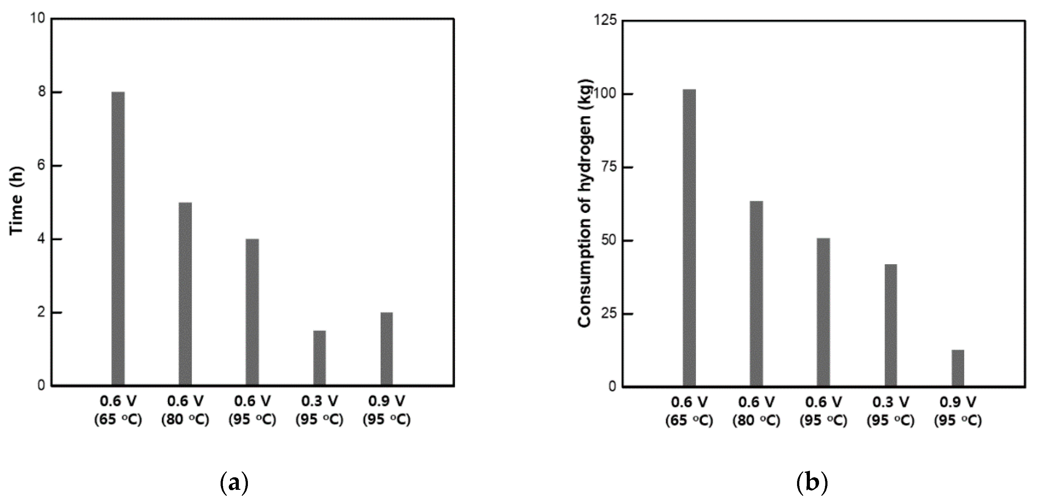
Economic analysis on the conditioning process was conducted to confirm the advantages of our suggested conditioning method by comparing it with previous methods. To this end, we analyzed the amount and cost of hydrogen used for conditioning a 135 kW PEM fuel cell stack (i.e., the same class as Hyundai’s NEXO). The elapsed time and consumption of hydrogen required to reach complete conditioning are shown in Figure 8. Moreover, the cost of hydrogen required for complete conditioning for each method is shown in Table 3. The newly proposed optimized conditioning method, i.e., conditioning based on the CV mode at 0.9 V with an operating temperature of 95 °C, was compared with conditioning based on the CV mode at 0.6 V with the operating temperature of 65 °C which was performed by Ko et al. [3]. For that study, approximately 101.54 kg of hydrogen were used for conditioning at 65 °C in the CV mode at 0.6 V. However, when conditioning at 95 °C in the CV mode at 0.9 V, only approximately 12.7 kg of hydrogen was used. Therefore, the optimized conditioning method reduced the consumption of hydrogen during conditioning by approximately 87.5%. Furthermore, the cost of hydrogen required to complete the conditioning process was also decreased by 955,622 KRW based on the current price of hydrogen in Korea [28]. Moreover, as shown in Table 4, the cost of hydrogen required to complete conditioning was also decreased by 1,243 USD, 97,734.12 JPY and 844.07 EUR based on the current hydrogen prices in the USA, Japan and Germany [29,30], respectively. This study intends to contribute to securing market accessibility by suggesting an optimal method of conditioning using the CV mode at 0.9 V with an operating temperature of 95 °C, to help save the unit price of fuel cells as discussed.
4. Conclusions
In this investigation, we conducted a parametric study to develop an optimal online conditioning method of the PEM fuel cell that was especially focused on developing the most economical method.
In the case of PEM fuel cell conditioning, regardless of conditioning in the CC or CV modes, the difference in performance improvement was less than 4.1%, so there was no difference in performance after conditioning. In the case of conditioning carried out at high potential differences (>0.6 V), the carbon support oxidation reaction causes the catalyst to become rearranged, resulting in TPB increase and rapid conditioning [24,25].
For conditioning, the CV mode required less time required for complete conditioning than the CC mode, with more than one hour of difference at the same load (e.g., 0.6 A/cm2 at 0.6 V). In addition, for conditioning, it was fastest to condition at a higher temperature of 95 °C. For CV mode conditioning with the operating temperature of 95 °C, conditioning at 0.3 V was 30 minutes faster than that at 0.9 V, but for the cost of hydrogen required to reach complete conditioning, conditioning at 0.9 V was 3.3 times less expensive per hour. When using the optimal method proposed by this study, i.e., conditioning CV mode at 0.9 V at 95 °C, the consumption of hydrogen required for complete conditioning can be reduced by 87.5%, compared to that when using the method performed by Ko et al. [3]. Furthermore, savings of 955,622 KRW, 1,243 USD, 97,734.12 JPY and 844.07 EUR based on the current hydrogen price in each country could be financially achieved by utilizing this proposed optimal conditioning method [28,29,30].
In conclusion, conditioning of PEM fuel cells was found to be the most economical when running at high potential differences and high operating temperature in the CV mode. This study suggests an optimal conditioning method designed to lower the actual production cost of fuel cells, thereby ensuring market access. Moreover, these discoveries enhance the understanding of the conditioning mechanism and have practical value that is important to the development of the fuel cell industry.
Author Contributions
Conceptualization, M.S.K.; methodology, J.H.S.; validation, M.S.K. and D.K.K.; formal analysis, M.S.K.; investigation, J.H.S.; writing—original draft preparation, M.S.K.; writing—review and editing, J.H.S. and D.K.K.; All authors have read and agreed to the published version of the manuscript.
Funding
This research was supported by the Chung-Ang University Research Scholarship Grants in 2018. This research was supported by Basic Science Research Program through the National Research Foundation of Korea (NRF) funded by the Ministry of Education (No. 2019R1F1A105803612).
Conflicts of Interest
The authors declare no conflict of interest.
References
- Kim, M.S.; Kim, D.K. Parametric study on dynamic heat and mass transfer response in polymer electrolyte membrane fuel cell for automotive applications. Appl. Therm. Eng. 2020, 167, 114729. [Google Scholar] [CrossRef]
- Xu, Z.; Qi, Z.; He, C.; Kaufman, A. Combined activation methods for proton-exchange membrane fuel cells. J. Power Sources 2006, 156, 315–320. [Google Scholar] [CrossRef]
- Ko, J.-J.; Ko, H.-J.; Song, M.-K.; Yang, Y.-C.; Lee, J.-H. Activation of polymer electrolyte membrane fuel cells. Korean Soc. New Renew. Energy 2005, 1, 30–40. [Google Scholar]
- Murthy, M.; Sisofo, N.T.; Baczowski, C.A. Method and Device to Improve Operation of a Fuel Cell. U.S. Patent 11/043,917, 27 July 2006. [Google Scholar]
- Economy, Hydrogen. Roadmap on Manufacturing R&D for the Hydrogen Economy. DOE Hydrogen Program; 2005; ISBN 0309097304. Available online: https://www.energy.gov/sites/prod/files/2014/03/f12/roadmap_manufacturing_hydrogen_economy.pdf (accessed on 2 June 2020).
- Yuan, X.Z.; Zhang, S.; Sun, J.C.; Wang, H. A review of accelerated conditioning for a polymer electrolyte membrane fuel cell. J. Power Sources 2011, 196, 9097–9106. [Google Scholar] [CrossRef] [Green Version]
- Lim, T.W.; Kim, S.H.; Ahn, S.Y.; Hong, B.K.; Ahn, B.K. System and Method for Activating Fuel Cell. U.S. Patent 8,455,121 B2, 4 June 2008. [Google Scholar]
- Hallum, R. Preconditioning Membranes of a Fuel Cell Stack. U.S. Patent 6,576,356 B1, 10 June 2003. [Google Scholar]
- Palanichamy, K.; Prasad, A.K.; Advani, S.G. Off-Line Conditioning of PEM Fuel Cell Membrane Electrode Assembly (MEA). ECS Meet. Abstr. 2008. [Google Scholar] [CrossRef]
- Xing, B.; Savadogo, O. Hydrogen/oxygen polymer electrolyte membrane fuel cells (PEMFCs) based on alkaline-doped polybenzimidazole (PBI). Electrochem. Commun. 2000, 2, 697–702. [Google Scholar] [CrossRef]
- Qi, Z.; Kaufman, A. Enhancement of PEM fuel cell performance by steaming or boiling the electrode. J. Power Sources 2002, 109, 227–229. [Google Scholar] [CrossRef]
- Anderson, B.P. Preconditioning Fuel Cell Membrane Electrode Assemblies. U.S. Patent 7,608,118 B2, 27 October 2009. [Google Scholar]
- Kim, J.-H.; Lee, H.-I.; Bae, B.; Yong Ha, H.; Shukla, A.K.; Christensen, P.A.; Dickinson, A.J.; Hamnett, A. Electrochemical Analysis of the Pre-Conditioning Effects on DMFC Performance. Electrochim. Acta 1983, 45. [Google Scholar]
- Cho, K.Y.; Jung, H.Y. Application of CV cycling to the activation of the polymer electrolyte membrane fuel cell. Appl. Chem. Eng. 2012, 23, 445–449. [Google Scholar]
- Luo, M.J.; Luo, Z.P.; Pan, M. Study on activation process of a PEM fuel cell stack. Wuhan Ligong Daxue Xuebao/Journal Wuhan Univ. Technol. 2006, 28, 499–502. [Google Scholar]
- Weng, F.B.; Jou, B.S.; Su, A.; Chan, S.H.; Chi, P.H. Design, fabrication and performance analysis of a 200 W PEM fuel cell short stack. J. Power Sources 2007, 171, 179–185. [Google Scholar] [CrossRef]
- Qi, Z.; Kaufman, A. Activation of Electrochemical Cells with Catalyst Electrodes. U.S. Patent 6,805,983 B1, 19 October 2004. [Google Scholar]
- Qi, Z.; Kaufman, A. Quick and effective activation of proton-exchange membrane fuel cells. J. Power Sources 2003, 114, 21–31. [Google Scholar] [CrossRef]
- Qi, Z.; Kaufman, A. Activation of low temperature PEM fuel cells. J. Power Sources 2002, 111, 181–184. [Google Scholar] [CrossRef]
- He, C.; Qi, Z.; Kaufman, A. Electrochemical Method to Improve the Performance of H2/Air Pem Fuel Cells and Direct Methanol Fuel Cells. U.S. Patent 6,730,424 B1, 4 May 2004. [Google Scholar]
- Kim, D.K.; Jung Choi, E.; Ho Song, H.; Soo Kim, M. Experimental and numerical study on the water transport behavior through Nafion® 117 for polymer electrolyte membrane fuel cell. J. Memb. Sci. 2016, 497, 194–208. [Google Scholar] [CrossRef]
- Yeager, E.B. 4. SOLID POLYMER ELECTROLYTE FUEL CELLS (SPEFCs). Energy 1986, 11, 137–152. [Google Scholar]
- Kim, J. Modeling of Proton Exchange Membrane Fuel Cell Performance with an Empirical Equation. J. Electrochem. Soc. 1995, 142, 2670. [Google Scholar] [CrossRef]
- Debe, M. Advanced cathode catalysts and supports for PEM fuel cells. Hydrog. Progr. Annu. Merit Rev. 2010, 790–798. [Google Scholar] [CrossRef] [Green Version]
- Pandy, A.; Yang, Z.; Gummalla, M.; Atrazhev, V.V.; Kuzminyh, N.Y.; Sultanov, V.I.; Burlatsky, S. A Carbon Corrosion Model to Evaluate the Effect of Steady State and Transient Operation of a Polymer Electrolyte Membrane Fuel Cell. J. Electrochem. Soc. 2013, 160, F972–F979. [Google Scholar] [CrossRef] [Green Version]
- Liu, J.; Hou, Z. Carbon Corrosion in Polymer Electrolyte Membrane Fuel Cell Catalysts and its Mitigation Strategies. In Eco- and Renewable Energy Materials; Springer: Berlin/Heidelberg, Germany, 2013; pp. 53–72. [Google Scholar]
- Uribe, F.A.; Zawodzinski, T.A. A study of polymer electrolyte fuel cell performance at high voltages. Dependence on cathode catalyst layer composition and on voltage conditioning. Electrochim. Acta 2002, 47, 3799–3806. [Google Scholar] [CrossRef]
- H2 Korea. Pricing of Transport Hydrogen Fuel and Establishment of Supply and Demand System; The Ministry of Trade, Industry and Energy (MOTIE): Sejong, Korea, 2018.
- Hong, S.A. Domestic Hydrogen Production, Consumption and Distribution Status Report; Gwangju Institute of Science and Technology (GIST): Gwangju, Korea, 2018. [Google Scholar]
- McKinney, J.; Bond, E.; Crowell, M.; Odufuwa, E. Assessment of Time and Cost Needed to Attain 100 Hydrogen Refueling Stations in California; California Energy Commission: Sacramento, CA, USA, 2015.
Figure 1.
Triple phase boundary of membrane electrode assembly (a) before online conditioning; and (b) after online conditioning.
Figure 1.
Triple phase boundary of membrane electrode assembly (a) before online conditioning; and (b) after online conditioning.

Figure 2.
(a) Schematic of the polymer electrolyte membrane (PEM) fuel cell experiment; and (b) photograph of the experimental equipment.
Figure 2.
(a) Schematic of the polymer electrolyte membrane (PEM) fuel cell experiment; and (b) photograph of the experimental equipment.

Figure 3.
Performance improvement of constant current (CC) mode conditioning depending on activation time.
Figure 3.
Performance improvement of constant current (CC) mode conditioning depending on activation time.

Figure 4.
Performance improvement of constant voltage (CV) mode conditioning depending on activation time.
Figure 4.
Performance improvement of constant voltage (CV) mode conditioning depending on activation time.

Figure 5.
Comparison of PEM fuel cell performance after conditioning between CC and CV modes.

Figure 6.
Principle of difference between (a) CV and (b) CC modes in the conditioning process.

Figure 7.
Conditioning of PEM fuel cell depending on operating temperature.

Figure 8.
(a) Time required for complete conditioning; and (b) consumption of hydrogen during the complete conditioning process.
Figure 8.
(a) Time required for complete conditioning; and (b) consumption of hydrogen during the complete conditioning process.


Table 1.
Carbon oxidation reaction of carbon support.
| Expression |
|---|
| C → C+(s) + e− |
| C+(s) + H2O → COsurf + 2H+ + e− |
| COsurf + H2O → CO2 + 2H+ +2e− |
Table 2.
Time required for complete conditioning.
| Conditioning Protocols | Time (h) |
|---|---|
| CC of 1.32 A/cm2 | 3 h |
| CC of 0.60 A/cm2 | 8 h |
| CC of 0.03 A/cm2 | 4 h |
| CV of 0.3 V | 2 h |
| CV of 0.6 V | 5 h |
| CV of 0.9 V | 2 h |
Table 3.
Cost of hydrogen during the complete conditioning process.
| Conditioning Protocols | Cost (KRW) |
|---|---|
| CV of 0.6 V at 65 °C [3] | 1,092,185 |
| CV of 0.6 V at 80 °C | 682,616 |
| CV of 0.6 V at 95 °C | 546,093 |
| CV of 0.3 V at 95 °C | 450,526 |
| CV of 0.9 V at 95 °C | 136,523 |
Table 4.
International cost of hydrogen (per kg of hydrogen).
| Nation | Cost |
|---|---|
| Korea | 10,756 KRW |
| USA | 13.99 USD |
| Germany | 9.5 EUR |
| Japan | 1,100 JPY |
© 2020 by the authors. Licensee MDPI, Basel, Switzerland. This article is an open access article distributed under the terms and conditions of the Creative Commons Attribution (CC BY) license (http://creativecommons.org/licenses/by/4.0/).
Share and Cite
MDPI and ACS Style
Kim, M.S.; Song, J.H.; Kim, D.K. Development of Optimal Conditioning Method to Improve Economic Efficiency of Polymer Electrolyte Membrane (PEM) Fuel Cells. Energies 2020, 13, 2831. https://doi.org/10.3390/en13112831
AMA Style
Kim MS, Song JH, Kim DK. Development of Optimal Conditioning Method to Improve Economic Efficiency of Polymer Electrolyte Membrane (PEM) Fuel Cells. Energies. 2020; 13(11):2831. https://doi.org/10.3390/en13112831
Chicago/Turabian StyleKim, Min Soo, Joo Hee Song, and Dong Kyu Kim. 2020. "Development of Optimal Conditioning Method to Improve Economic Efficiency of Polymer Electrolyte Membrane (PEM) Fuel Cells" Energies 13, no. 11: 2831. https://doi.org/10.3390/en13112831
Note that from the first issue of 2016, this journal uses article numbers instead of page numbers. See further details here.